


By: Arif Khan.
According to Thevenin’s Theorem, a voltage source connected in series with a resistor can be used to represent any two-terminal linear network or circuit. Independent sources, dependent sources, and resistors are all possible components in a linear circuit.
The response of one element in a circuit with many independent sources, dependent sources, and resistors can be quickly determined by substituting Thevenin’s equivalent circuit for the complete network to the left of that element.
The voltage across an element, the current flowing through it, or the power dissipated across it can all be considered the element’s response.
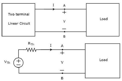
The corresponding circuit of Thevenin looks like a real-world voltage source. Consequently, it features a resistor in series with a voltage source.
- Thevenin’s equivalent voltage, abbreviated VTh, is the name given to the voltage source used in Thevenin’s equivalent circuit.
- Thevenin’s equivalent resistor, abbreviated as RTh, is the resistor that makes up Thevenin’s equivalent circuit.
Methods of Finding Thevenin’s Equivalent Circuit
Thevenin’s equivalent circuits can be discovered using one of three techniques. We can select one of these three approaches depending on the types of sources that are present in the network. Let’s now talk about 1st approach at this time. We will talk about each approach in separate blogs.
1st Method
When there are just independent type sources present, use these methods to find Thevenin’s equivalent circuit.
Step 1: Look at the circuit schematic while opening the terminals corresponding to the Thevenin equivalent circuit.
Step 2: Calculate Thevenin’s voltage VTh across the circuit’s open terminals.
Step 3: By removing the circuit’s independent sources, determine Thevenin’s resistance RTh across the open terminals.
Step 4: Connect the Thevenin voltage VTh and Thevenin resistance RTh in series to create the Thevenin equivalent circuit.
Now, the element on the right side of Thevenin’s equivalent circuit contains the response.
Example.
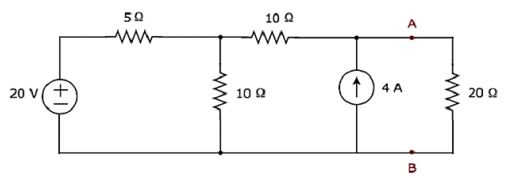
Step 1: By opening terminals A and B, we can take the 20 resistors out of the network and discover Thevenin’s equivalent circuit to the left of them. The following figure displays the changed circuit diagram.

Step 2 : Calculation of Thevenin’s voltage VTh.
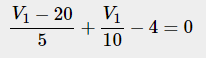
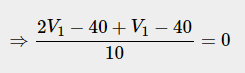
In the circuit described above, there is just one major node other than Ground. We can so employ the nodal analysis method. In the aforementioned figure, the node voltage V1 and Thevenin’s voltage VTh are labeled. Here, V1 is the voltage across the 4 A current source, and VTh is the voltage across node 1 with respect to the ground.
The nodal equation at node 1

Below is the voltage across the series branch 10Ω resistor

The circuit mentioned above consists of two meshes. The second mesh’s KVL equation is.

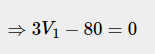
Substitute the values of V1 and V10Ω in the above equation.


So, the Thevenin’s voltage is VTh=200/3V
Step 3: Calculation of Thevenin’s resistance RTh
To determine the Thevenin’s resistance RTh across terminals A & B, short the voltage source and open the current source in the circuit above. The following figure displays the changed circuit diagram.

The resistance of the Thevenin between terminals A and B will be

So, Thevenin’s resistance is RTh=40/3Ω.
Step 4: The Thevenin’s equivalent circuit is positioned in the provided circuit to the left of terminals A and B. The following figure displays this circuit diagram.
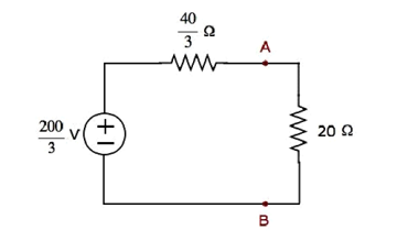
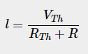
The current flowing through the 20Ω resistor can be found by substituting the values of VTh, RTh and R in the following equation.
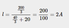
Therefore, the current flowing through the 20Ω resistor is 2A.


An intriguing discussion is definitely worth comment. I do think that you should write more on this subject matter, it may not be a taboo matter but usually people dont discuss these issues. To the next! Many thanks!!