


By: Arif Khan.
In electrical and electronic applications, a load’s power input is a crucial variable. In DC circuits, the load is represented by a resistor with RL ohms of resistance. Similar to this, we may represent it in AC circuits by using a complicated load with an impedance of ZL ohms.
According to the maximum power transfer theorem, the DC voltage source will only supply the variable load resistor with the maximum amount of power when the load resistance is equal to the source resistance.
Similar to this, according to the Greatest Power Transfer Theorem, the AC voltage source will only provide the variable complex load with the maximum amount of power when the load impedance is equal to the complex conjugate of the source impedance.
The maximum power transfer theorem to DC circuits will be discussed in this blog.
Maximum Power Transfer Theorem Proof
Any two terminal linear network or circuit that has a resistance of RL ohms should be replaced with a Thevenin’s equivalent circuit on the left side of the variable load resistor. Thevenin’s equivalent circuit is known to resemble a real-world voltage source.
See the below figures for an illustration.

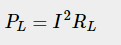
Power is lost across the load resistor at a rate of


Condition for Maximum Power Transfer
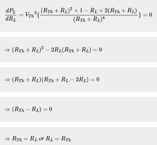
Consequently, RL=RTh is the need for maximal power dissipation over the load. In other words, the power dissipated across the load will be at its maximum if the value of load resistance is equal to the value of source resistance, or Thevenin’s resistance.
The value of Maximum Power Transfer

Consequently, the maximum power that may be delivered to the load is

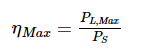
The efficiency of Maximum Power Transfer
Using the formula below, we may determine the efficiency of maximum power transmission or ηMax.
- PLMax is the maximum amount of power transferred to the load.
- PS is the amount of power generated by the source.
The source produces an amount of power that is


SubstiSubstitute the values of PL, and PS in Equation

We can represent the efficiency of maximum power transfer in terms of percentage as follows

As a result, 50% of maximum power is transferred efficiently.
Example
In the circuit indicated in the following picture, determine the maximum power that can be applied to the load resistor RL.

Step 1: We determined Thevenin’s equivalent circuit to the left of terminals A and B in the Thevenin’s Theorem chapter. This circuit is now functional. In the following figure, it is depicted.

Step 2: Substitute the aforementioned Thevenin’s equivalent circuit for the portion of the circuit that is located on the left side of terminals A and B in the given circuit. The following figure displays the resulting circuit diagram.

Step 3: Using the following formula, we can determine the maximum power that will be transferred to the load resistor, RL.

In light of this, the maximum power that will be delivered to the given load resistor RL