


By: Arif Khan.
This site aims to arm readers with the talents necessary to dissect and repair any electric network or circuit. Once you’ll finish this session, you’ll comprehend the laws and procedures that can be used to analyze certain electric circuits and networks.
Audience
All readers who want to find out the principles of network theory should study this lesson. This course is additionally known as “Network Analysis & Circuit Theory” in various Colleges and Universities.
Prerequisites
The principles covered during this tutorial don’t require a lot of prior knowledge. you’ll feel comfortable with the techniques and concepts of the DC circuits and AC circuits, which will be discussed in later blogs, once you’ve got finished the first few blogs.
Theory
The study of circuit or network problems is known as Network Theory. Let’s first re-evaluate the fundamental terms used in electrical circuits and the many kinds of network components in this introductory blog.
Terminologies used in Electronics
The following terms are often used in network theory.
- Electric Circuit.
- Electric Network
- Current
- Voltage
- Power
Therefore, it’s essential that we get a foundational understanding of these words before moving on. Starting with the electrical circuit.
Electric Circuit
A closed path for supplying an electron be due a voltage source or current source exists in an electric circuit. an electrical circuit will have elements connected in series, parallel, or any combination of series and parallel connections.
Electric Network
There is no requirement that an electric network comprise a closed path for supplying an electron flow from a voltage source or current source. We can say that “all electric circuits are electric networks,” yet the opposite need not be true.
Current
The time rate of charge flow is what determines what proportion of current, or I, is flowing through a conductor. In mathematics, it’s going to be expressed as I = dQ/dt where Q is the charge and its unit is Columb and t is the time and its unit is second.
Voltage
Electromotive force or voltage “V” is what drives charge (or electrons) to flow. In mathematics, it’s going to be expressed as V = dW/dQ where W is the potential energy and its unit is Joule and Q is the charge and its unit is Columb
Voltage is often compared to the water pressure that propels water through a conduit in an analogous manner. Volt units are wont to measure it.
Power
The power “P” is the rate at which electrical energy flows over time. In mathematics, it’s going to be expressed as P = dW/dt where W is the electrical energy and it is measured in terms of Joule and t is the time measured in seconds.
We can mathematically re-write the said equation as P = dW/dt = dW/dQ x dQ/dt = VI Power is just the result of voltage (V) and current (I). Watt is its measure.
Types of Network Elements
Based on a few factors, we will divide the network elements into distinct categories. the kinds of network elements are as follows:
- Active Elements and Passive Elements
- Linear Elements and Non-linear Elements
- Bilateral Elements and Unilateral Elements
Active Elements and Passive Elements
Depending on their capacity to transmit power, network components are often divided into active or passive categories.
- Other elements in an electrical circuit that are present are given power by active elements. They occasionally may act as passive elements and absorb the facility. This suggests that active materials are able to both deliver and absorb power. Examples include current and voltage sources.
- While they can’t supply power (energy) to other elements, passive elements can absorb it. Means that these substances either release energy as heat or store it as an electrical or magnetic field, respectively. Examples: Resistors, Inductors, and capacitors.
Linear Elements and Non-Linear Elements
Based on their ability to adhere to the linearity property, we will categorize network elements as linear or non-linear.
- The elements that exhibit a linear connection between voltage and current are known as linear elements. Examples include capacitors, inductors, and resistors.
- The absence of a linear relationship between voltage and current may be a sign of a non-linear element. Examples include current and voltage sources.
Bilateral Elements and Unilateral Elements
Depending on the way current passes through network elements, they will alternatively be categorized as bilateral or unilateral.
Bilateral elements are people who offer the same impedance in both directions of current flow and permit current to flow in either direction. Examples include capacitors, inductors, and resistors.
The following figures provide examples of bilateral elements.

In the following diagram, a passive device with an impedance of Z is allowing current (I) to be due terminals A to B. The voltage (V) across that element between terminals A and B divided by the present (I).
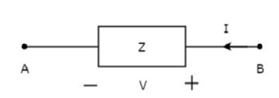
In the above diagram, a passive device with an impedance of Z is allowing current (I) to be due terminals B to A. this means that terminals A to B are where the current (-I) is moving. Since both the present and the voltage have negative signs relative to terminals A and B, we’ll obtain the same impedance value in this instance as well. Unilateral Elements are people who only permit one direction of current to flow. they supply various impedances in both directions as a result.