


By: Arif Khan.
Theory
Thevenin’s theorem and Norton’s are almost similar. It claims that any two-terminal linear network or circuit can be represented by an equivalent network or circuit that has a current source connected in parallel to a resistor. The Norton equivalent circuit is what it is called. Independent sources, dependent sources, and resistors are all possible components in a linear circuit.
If a circuit has a number of independent sources, dependent sources, and resistors, the response in a given element can be quickly determined by substituting Norton’s equivalent circuit for the complete network to the left of that element.
This concept is illustrated in the following figures.

A realistic current source mimics Norton’s comparable circuit. As a result, a resistor and a current source are connected in parallel.
- The current source present in Norton’s equivalent circuit is called as Norton’s equivalent current or simply Norton’s current IN.
- The resistor present in Norton’s equivalent circuit is called as Norton’s equivalent resistor or simply Norton’s resistor RN.
Methods of Finding Norton’s Equivalent Circuit
Norton’s equivalent circuit can be found in one of three ways. We can select one of these three approaches depending on the types of sources that are present in the network. Let’s now talk about each of these three approaches separately.
Method 1
When there are just independent type sources present, use these techniques to find Norton’s equivalent circuit.
Step 1: Open the terminals on the circuit schematic and think about where Norton’s equivalent circuit should be.
Step 2: Short the two open terminals of the aforementioned circuit to determine Norton’s current IN.
Step 3: By removing all of the circuit’s independent sources, determine Norton’s resistance RN across the open terminals. The resistance RN of Norton and Thevenin will be identical.
Step 4: Create the Norton equivalent circuit by joining a Norton current IN and a Norton resistance RN in parallel.
Now, we may locate the answer in a component that is located on Norton’s analogous circuit’s right side.
Method 2
When there are both independent and dependent type sources present, use these techniques to find Norton’s equivalent circuit.
Step 1: Open the terminals on the circuit schematic and think about where Norton’s equivalent circuit should be located.
Step 2: Measure the voltage across the circuit’s open terminals to get the open circuit voltage (VOC).
Step 3: Short the two open terminals of the circuit above to determine Norton’s current IN.
Step 4: Apply the formula below to determine Norton’s resistance number (RN).
Step 5: Create Norton’s equivalent circuit by joining the Norton resistance RN and Norton current IN in parallel.
Now, we may locate the answer in a component that is located on Norton’s analogous circuit’s right side.
Method 3
This alternative approach can be used to identify Norton’s equivalent circuit.
Step 1: Find a Thevenin’s equivalent circuit between the two terminals you want. We are aware that it comprises of a Thevenin resistor, RTh, and a Thevenin voltage source, VTh.
Step 2: Apply the source transformation approach to Thevenin’s equivalent circuit. The Norton’s equivalent circuit will be provided.
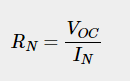
Norton’s current

Norton’s resistance

This concept is illustrated in the following figure.

Now, by positioning Norton’s equivalent circuit to the left of an element, we may determine the response in that element.
Note: In a similar manner, by first locating Norton’s equivalent circuit and then using the source transformation technique on it, we can identify Thevenin’s comparable circuit. The following figure provides an illustration of this idea.

This is Method 3 for finding Thevenin’s equivalent circuit.
Example

Let’s use Method 3 to resolve this issue.
Step 1: Thevenin’s equivalent circuit to the left of terminals A and B was calculated in the preceding chapter. This circuit is now functional. In the following figure, it is depicted.


Step 2: Apply the source transformation approach to Thevenin’s equivalent circuit. Replace VTh and RTh numbers in the following Norton’s current formula.

Norton’s current IN is therefore 5 A.
We are aware that Thevenin’s resistance RTh and Norton’s

The following figure depicts Norton’s equivalent circuit that corresponds to Thevenin’s equivalent circuit mentioned above.

Now, position Norton’s equivalent circuit to the left of the supplied circuit’s terminals A and B.

The current going through the 20 resistors will be (using the current division principle)
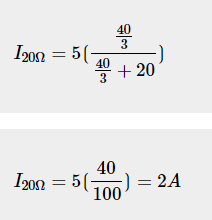
Therefore, the current flowing through the 20 Ω resistor is 2 A.